UBC Engineering Physics · ENPH 459 · Project 2510
Vehicle RF monitoring
for radio astronomy.
A camera-triggered radio-frequency noise monitor for the Dominion Radio Astrophysical Observatory (DRAO), built to associate passing vehicles with their spectral signatures near CHIME.
- Project
- Sep 2024–Apr 2025 · Four-person team
- Research context
- CHIME · DRAO
UBC Experimental Cosmology Lab - Sponsors
- Dr. Mark Halpern · Dr. Gary Hinshaw
Mr. Parham Zarei
A motion trigger preserves camera footage and starts a timestamped measurement.
SDR sweeps cover the 400–800 MHz band of interest, beyond one instantaneous capture.
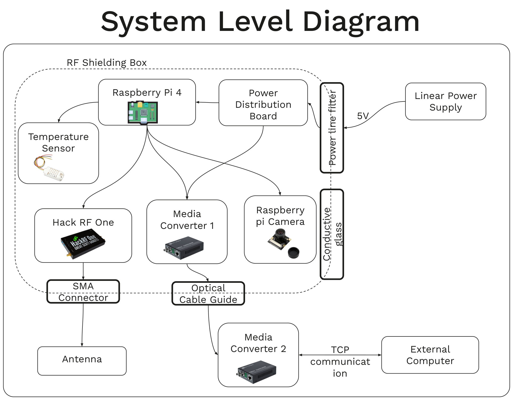
Shielding, filtered power, and a fiber link reduce the monitor’s own interference.
Requirements · System architecture
Find the source without becoming one
CHIME observes extremely faint astronomical signals in the 400–800 MHz band. Our sponsors wanted to investigate whether nearby vehicles were contributing radio-frequency interference to those observations. The engineering challenge was to collect useful evidence while preventing the monitoring electronics themselves from becoming another source of noise.
We combined two measurements: a camera records when a vehicle is present, and an antenna with a software-defined radio (SDR) records the spectrum around that event. A Raspberry Pi coordinates acquisition inside a shielded enclosure. An optical link carries the data to an external computer for storage and inspection.
 Full size
Computer vision · Embedded acquisition
Turn vehicle motion into a recorded event
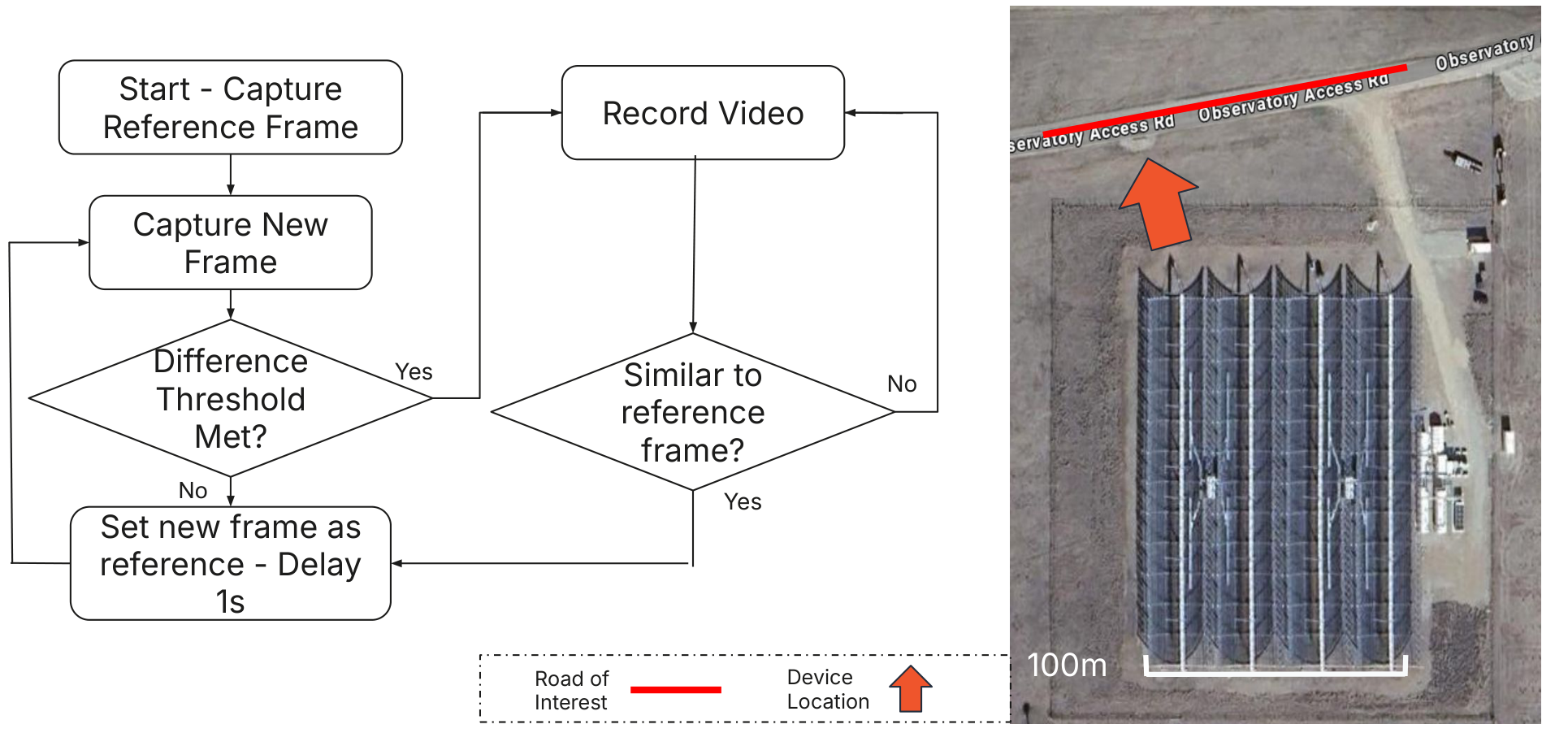
We chose classical image processing to fit the Raspberry Pi’s compute budget. The fisheye camera supplies frames through Picamera2; an updated reference image and a difference threshold identify motion. This is a motion-based trigger for vehicle monitoring, rather than a learned vehicle classifier.
 Full size
A circular video buffer preserves footage from before the trigger. Once motion is detected, the system creates an event, records its timestamp and environmental readings, and initiates RF acquisition. This provides visual context for interpreting a spectral change rather than treating every RF transient as a confirmed vehicle emission.
Software-defined radio · FFT · Signal processing
Build a wideband view from narrowband measurements
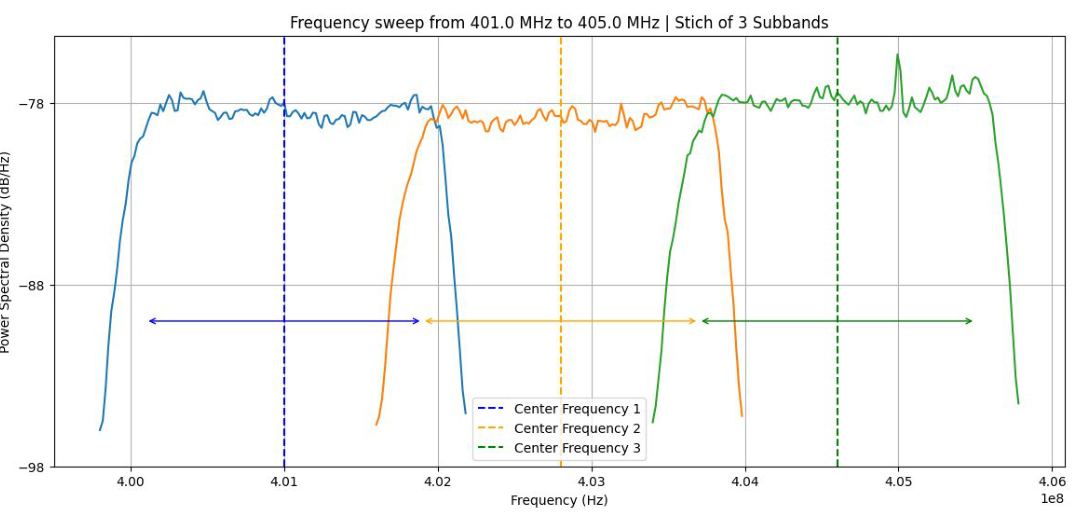
Early experiments used an RTL-SDR to check whether car-associated spectral changes were detectable. The final system used a HackRF One with up to 20 MHz instantaneous bandwidth. Since the target band spans 400 MHz, a single capture cannot cover it: the receiver steps through center frequencies, measures overlapping sub-bands, and stitches their usable portions together.
 Full size
Processing each capture
- Acquire complex IQ samples at a selected center frequency.
- Compute the FFT and squared magnitude.
- Normalize for sampling rate and FFT length to estimate spectral density.
- Shift the frequency axis and express power on a logarithmic scale.
- Retain usable bins and assemble the sweep on an RF frequency axis.
A measurement artifact is not a vehicle signal
Local-oscillator leakage creates a spike near each capture’s center frequency. The report’s processing method excludes affected center bins and trims band edges, using shifted, overlapping captures to recover coverage. This was a practical lesson in separating receiver artifacts from the signal being measured.
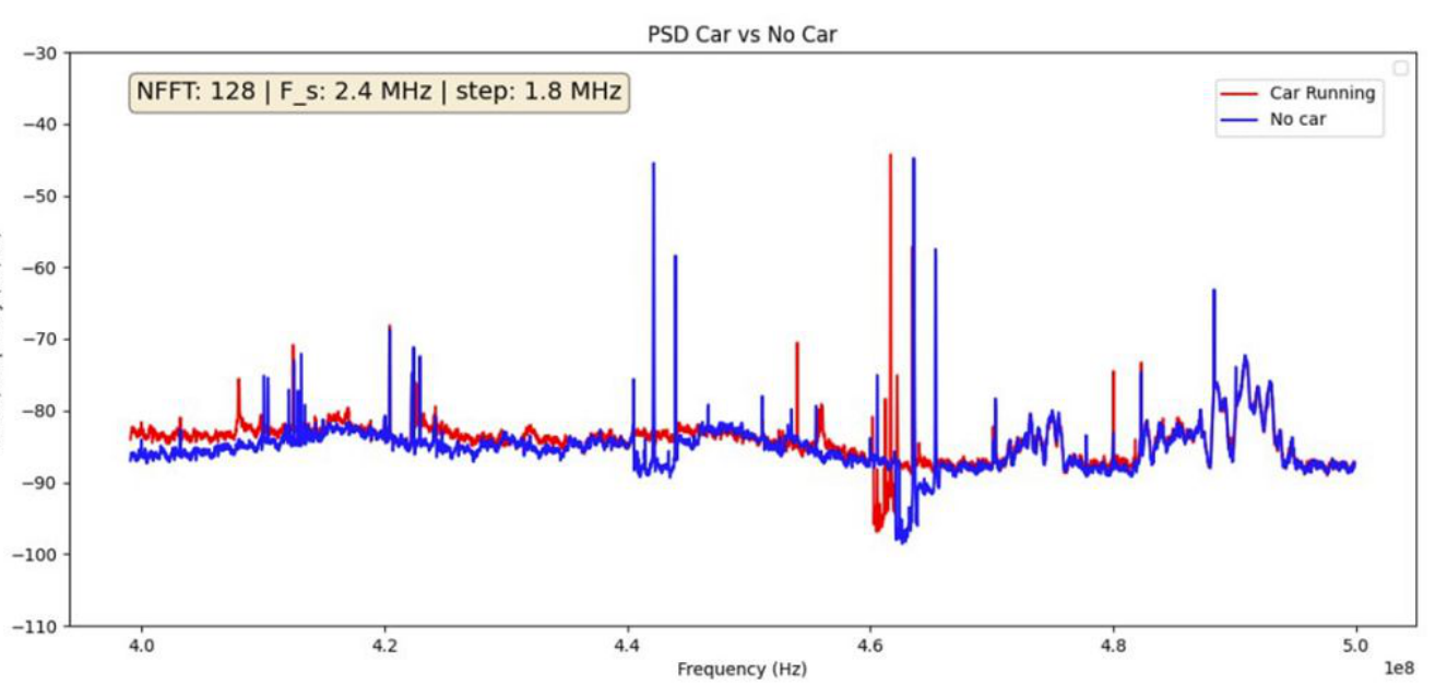
A sweep samples different frequencies at different times. That tradeoff matters for transient vehicle emissions: wider coverage comes at the expense of temporal resolution. The presentation’s 2.4 MHz examples use the early RTL-SDR; the final report describes the later HackRF system.
Mechanical packaging · EMI control · Power integration
Engineer the enclosure around every opening
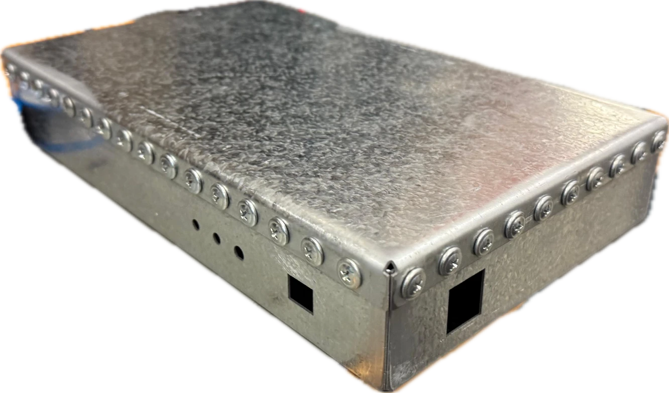
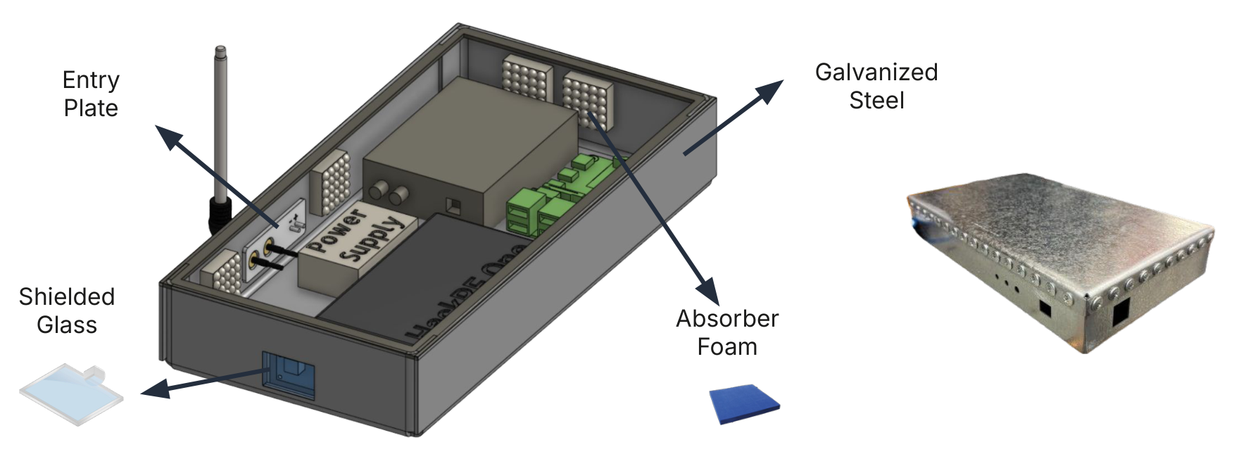
The enclosure had to contain noise from the Pi, SDR, and networking electronics while allowing camera access, antenna input, power, and data connections. The fabricated design used 1 mm galvanized steel, a removable lid fastened with 54 screws, and conductive treatment of seams and contact surfaces.
 Full size
| Interface | Engineering approach |
|---|---|
| Data | Ethernet-to-fiber media converters provide remote connectivity. A copper waveguide feedthrough carries the fiber while limiting RF leakage through the opening. |
| Power | A linear supply and inline power filters reduce switching and conducted noise. An undervoltage-lockout circuit cuts power near 4.7 V as the supply decays. |
| Antenna | An enclosure-grounded SMA connection brings the external RF signal to the receiver. |
| Camera | A conductive window is required to retain optical visibility while completing the shielding boundary. |
| Environment | DHT22 temperature/humidity logging supports diagnostics. Outdoor operation was a design goal, with further weather and thermal qualification still required. |
The removable lid made integration and testing possible without permanently sealing the instrument. Its seams were also potential leakage paths, so mechanical serviceability and RF continuity had to be designed together.
Python architecture · State machines · TCP · PyQt5
Connect the measurement to the researcher
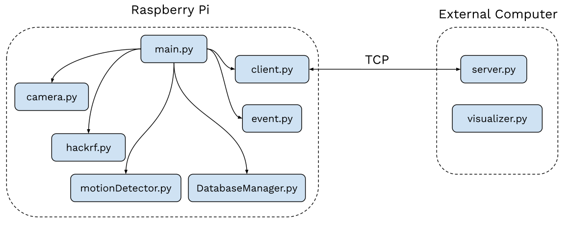
The software organizes hardware access, event capture, storage, and remote communication into separate Python classes. A state machine coordinates the sequence from waiting for motion to sweeping, transferring files, updating the database, and housekeeping.
 Full size
Acquisition and persistence
Camera and HackRF interfaces encapsulate hardware control. Event and Sweep objects organize metadata; SQLite indexes recorded events. Configuration files centralize acquisition settings, while structured logging and virtual sensors support diagnostics and development away from the Pi.
Remote inspection
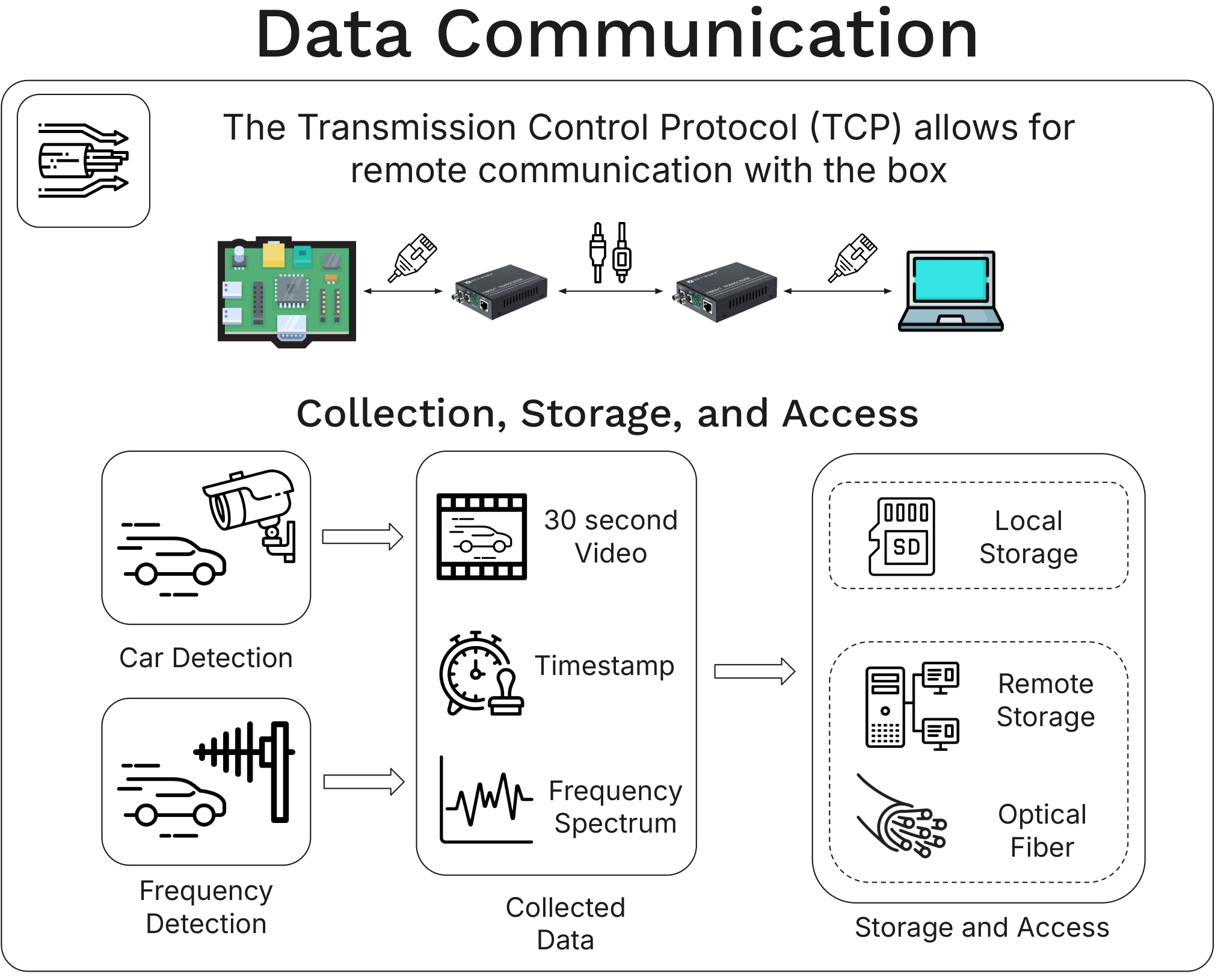
A TCP client/server connection transfers IQ recordings, video, and JSON metadata over the optical link. The PyQt5 application supports historical event review and live camera/spectrum access through a Pi-side listener, including receiver gain and sample-rate controls.
 Full size
TCP was chosen for ordered, reliable delivery of large recordings and control messages. The optical link addresses the physical interference constraint; TCP addresses transport reliability. These solve different parts of the system problem.
Experimental validation · Measurement limits
Validate the signal—and the instrument
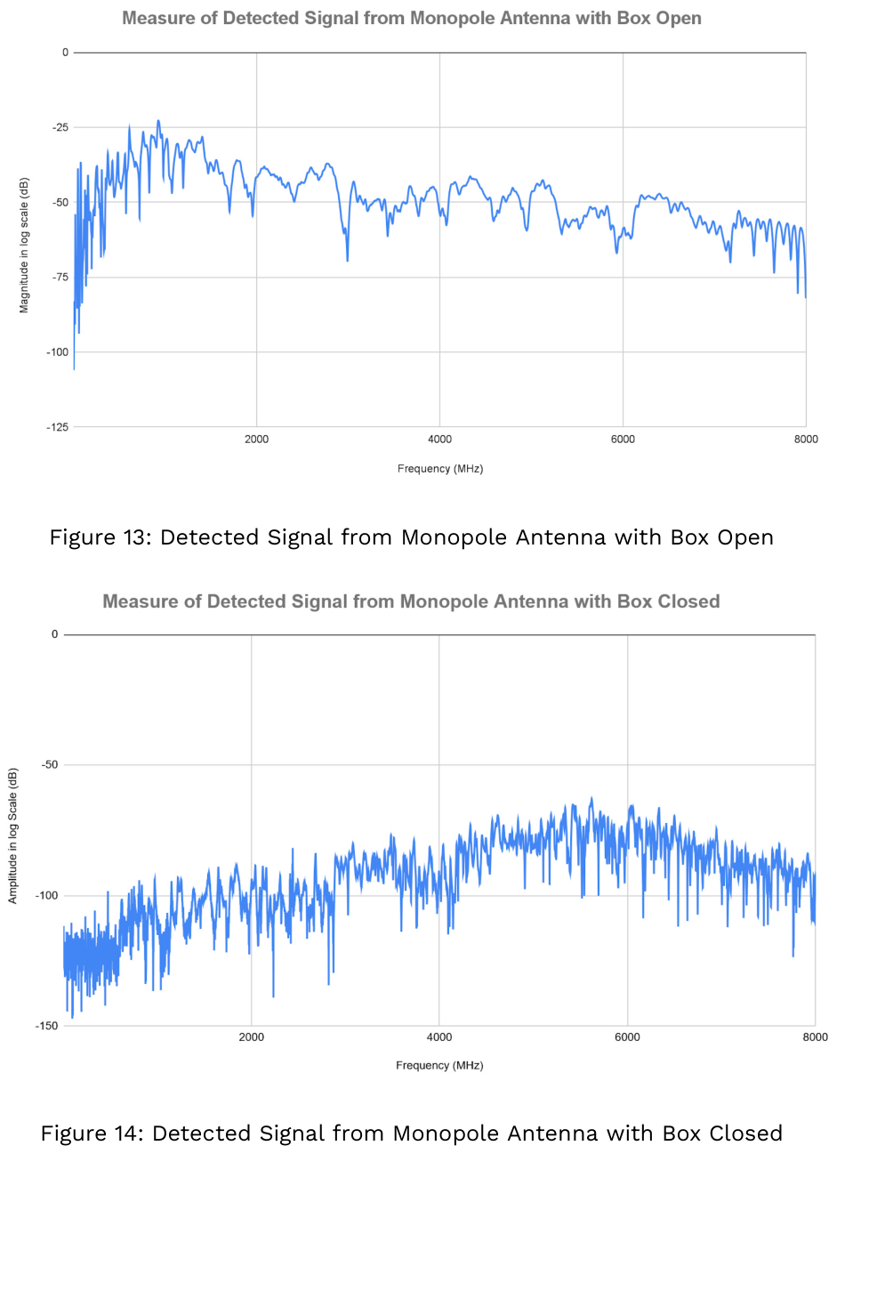
The experiments compared vehicle-present and background spectra, then separately tested the enclosure’s shielding. Keeping those tests distinct matters: observing a spectral difference and proving that the measurement system is sufficiently quiet are separate engineering questions.
 Full size
 Full size
| Area | What the project established |
|---|---|
| RF acquisition | Car-associated spectral changes were observed, and a sweep/stitch pipeline was implemented. Better accuracy and temporal coverage remained research directions. |
| Integration | A fabricated enclosure and modular acquisition, logging, TCP transfer, and PyQt inspection stack were developed and demonstrated. |
| Shielding | The report documents strong suppression in the sealed-box test. Installing and testing the camera’s conductive window remained necessary before deployment. |
| Outdoor operation | A sealed-prototype thermal test informed the design. Long-term outdoor reliability across the intended temperature range was not yet validated. |
Skills developed through the project
This project connected RF measurement to a complete software and hardware workflow. It developed my experience with SDR acquisition, FFT-based spectral analysis, Python device interfaces, event-driven control, TCP networking, and PyQt visualization, alongside the practical constraints of an RF-sensitive instrument.
The work also reinforced a broader engineering habit: distinguish design targets from measured results, and interpret experimental data in the context of bandwidth, receiver artifacts, and the test setup.
Next steps from the final report
Complete the path to field deployment
- Install conductive camera glass and revalidate the complete enclosure.
- Improve spectral accuracy and acquisition speed; investigate higher-bandwidth receiver approaches.
- Perform extended outdoor thermal and weather testing.
- Refine higher-frequency shielding and adapt the monitoring workflow to DRAO’s operational needs.
The project team
Instrumentation built collaboratively
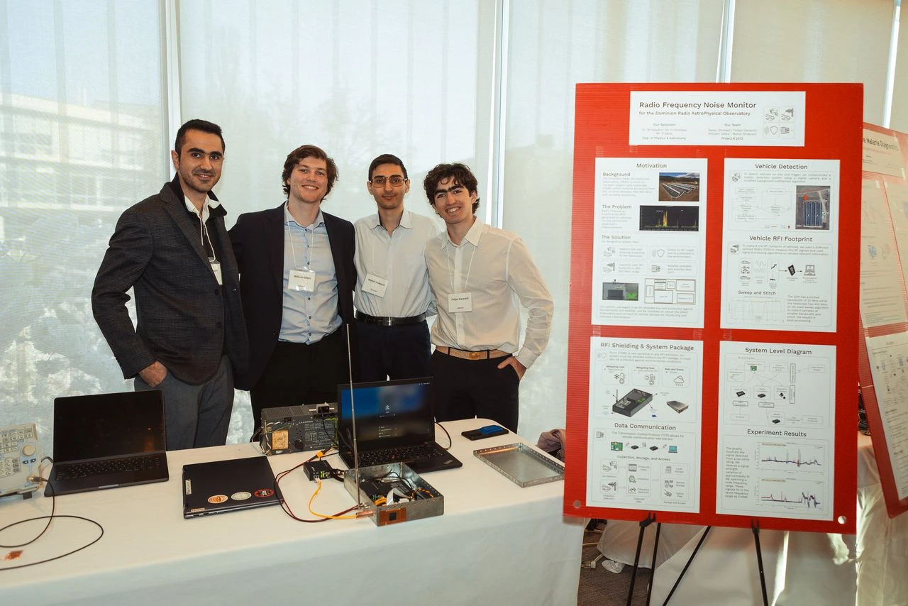
Developed by Sasan Ghasaei, William Gibbs, Mahdi Shakouri Ganjavi, and Felipe Garavelli for UBC Engineering Physics, with sponsors Dr. Mark Halpern, Dr. Gary Hinshaw, and Mr. Parham Zarei.
The system design and results presented here reflect the four-person team’s work.
 Full size